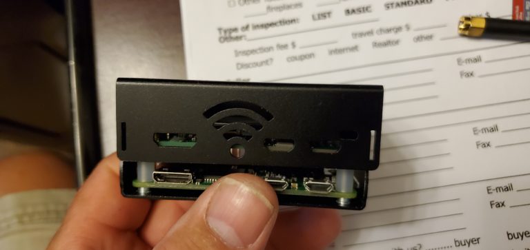

I soldered the step-down converter, Darlington driver, and input resistors to a prototype board and mounted it to the inside wall of the plastic enclosure. Raspberry Pi Zero mounted in plastic enclosure, GPIO connected Probably best explained by the schematic drawing. The inputs have 10K pull-up resistors, with 330 in series with the Raspberry Pi GPIO input. The Raspberry Pi doesn’t have 5V on its GPIO, it has 3.3V, but I found this works just as well with the ULN2003A. It is pretty much perfect for this application it is compact, has base resistors, and take 5V on the inputs. Raspberry Pi Zero powered by step-down converterįor the outputs, I’m using a Darlington driver, ULN2003A. I’m using 12V as input, as that will power all the LEDs, the buzzer, and the strobe. To power the Raspberry Pi Zero, I am using a 5V step-down converter, connected to the micro USB port on the Raspberry Pi. I have written a post about that, where I go into details on how to get the Raspberry Pi ready, so I won’t cover that here.

Raspberry Pi Zero connectedįirst, I needed to get the Raspberry Pi up and running. And I can program in Python, which I rather enjoy. With a couple of switches, some panel indicators, a buzzer, and a blue LED strobe.Īn advantage of using a Raspberry Pi, instead of e.g., Arduino, is that I can easily SSH into it and modify the code. I needed an excuse to use the Raspberry Pi Zero in a project, so I built them a WiFi MQTT controlled alarm module. My twin boys are, like their dad, fascinated by switches and flashing lights.


 0 kommentar(er)
